 Honda CBR125RW - Service manual > Cylinder Head/Valves
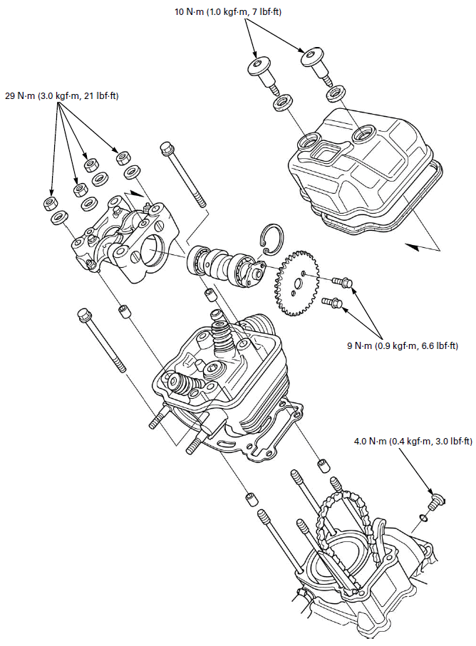
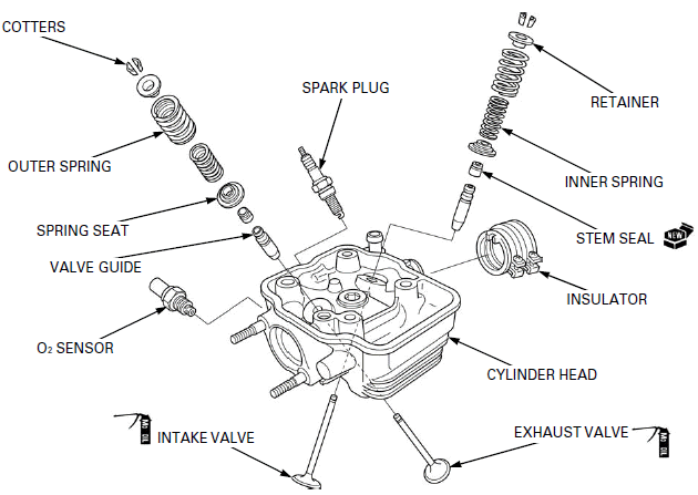
COMPONENT LOCATION
SERVICE INFORMATION
GENERAL
- This section covers service of the cylinder head, valves, rocker arms and camshaft.
- The camshaft service can be done with the engine installed in the frame. The cylinder head service requires engine removal.
- Be careful not to damage the mating surfaces when removing the cylinder head cover and cylinder head. Do not strike the cylinder head cover and cylinder head too hard during removal.
- When disassembling, mark and store the disassembled parts to ensure that they are reinstalled in their original locations.
- Clean all disassembled parts with cleaning solvent and dry them by blowing them off with compressed air before inspection.
- Camshaft and rocker arm lubricating oil is fed through oil passage in the cylinder head (stud bolt hole) and camshaft holder. Clean the oil passage before assembling them.
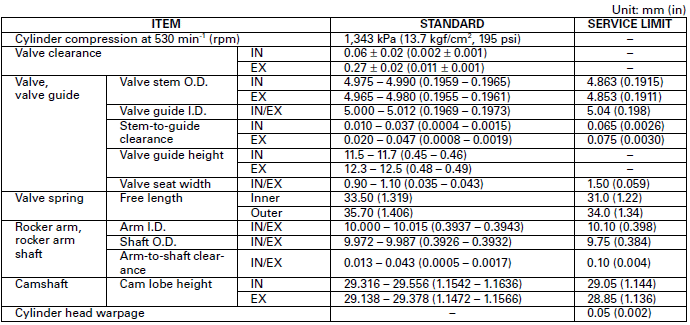
SPECIFICATIONS
TORQUE VALUES
Cylinder head cover bolt 10 N-m (1.0 kgf-m, 7 lbf-ft)
Rocker arm shaft stopper bolt 9.0 N-m (0.9 kgf-m, 6.6 lbf-ft)
Camshaft holder mounting nut 29 N-m (3.0 kgf-m, 21 lbf-ft) Apply engine
oil to the threads and seating surface.
Cam sprocket mounting bolt 9.0 N-m (0.9 kgf-m, 6.6 lbf-ft)
Cam chain tensioner lifter plug 4.0 N-m (0.4 kgf-m, 3.0 lbf-ft)
Insulator band screw -
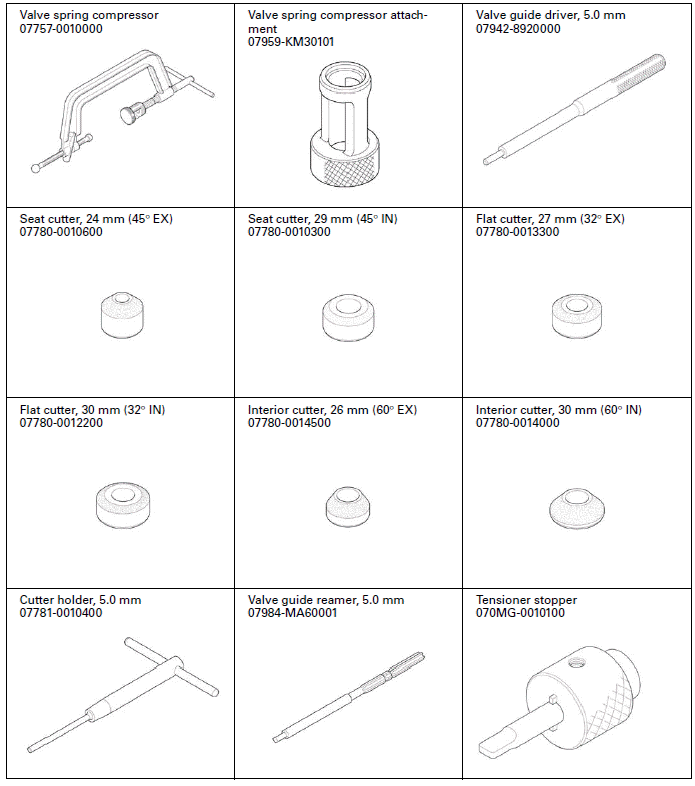
TOOLS
TROUBLESHOOTING
- Engine top-end problems usually affect engine performance. These problems can be diagnosed by a compression test, or by tracing top-end noise with a sounding rod or stethoscope.
- If the performance is poor at low speeds, check for white smoke in the crankcase breather hose. If the hose is smoky, check for a seized piston rings.
Compression too low, hard starting or poor performance al low speed
- Valves:
- Incorrect valve adjustment
- Burned or bent valve
- Incorrect valve timing
- Weak valve spring
- Uneven valve seating
- Valve stuck open
- Cylinder head:
- Leaking or damaged cylinder head gasket
- Warped or cracked cylinder head
- Loose spark plug
- Faulty cylinder, piston or piston rings.
Compression too high, over-heating or knocking
- Excessive carbon build-up on piston head or combustion chamber
Excessive smoke
- Worn valve stem or valve guide
- Damaged stem seal
- Faulty cylinder, piston or piston rings
Excessive noise
- Incorrect valve adjustment
- Sticking valve or broken valve spring
- Worn or damaged camshaft
- Worn rocker arm and/or shaft
- Worn rocker arm and valve stem end
- Worn cam sprocket teeth
- Worn and loose cam chain
- Worn or damaged cam chain tensioner
- Faulty cylinder, piston or piston rings
Rough idle
- Low cylinder compression
- Faulty fuel system
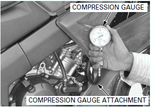
CYLINDER COMPRESSION
Warm the engine to normal operating temperature.
Stop the engine.
Remove the spark plug.
Install the compression gauge attachment into the spark plug hole.
Connect the compression gauge to the attachment.
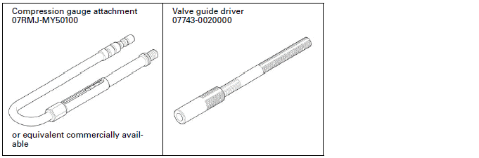
TOOL: Compression gauge attachment 07RMJ-MY50100 or equivalent commercially available
Turn the ignition switch ON (and engine stop switch " ":
CM and U type).
":
CM and U type).
Shift the transmission into neutral.
Crank the engine with the starter motor.
To avoid discharging the battery, do not operate the starter motor for more than 7 seconds.
Open the throttle all the way and crank the engine with the starter motor until the gauge reading stops rising.
STANDARD: 1,343 kPa (13.7 kgf/cm2, 195 psi) at 530 min-1(rpm)
Low compression can be caused by:
- Blown cylinder head gasket
- Improper valve adjustment
- Valve leakage
- Worn piston ring or cylinder
High compression can be caused by:
- Carbon deposits in combustion chamber or on piston head
CYLINDER HEAD COVER
REMOVAL
Remove the middle cowl.
The cylinder head cover can be serviced with the engine installed in the frame.
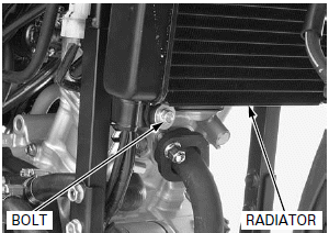
Remove the radiator lower mounting bolt, then move the radiator forward.
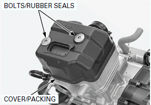
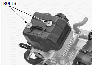
Remove the cylinder head cover bolts, rubber seals, cylinder head cover and packing.
INSTALLATION
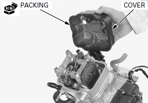
Install a new packing into the cylinder head cover groove.
Install the cylinder head cover onto the cylinder head.
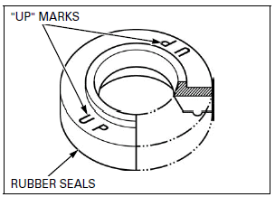
Check the rubber seals are in good condition, replace them if necessary.
Install the rubber seals to the cylinder head cover with their "UP" marks facing up.
Install and tighten the cylinder head cover bolts to the specified torque.
TORQUE: 10 N-m (1.0 kgf-m, 7 lbf-ft)
CAMSHAFT
The camshaft can be serviced with the engine installed in the frame.
Remove the cylinder head cover.
Make sure the piston is at TDC (Top Dead Center) on the compression stroke.
Loosen the lock nuts and adjusting screws.
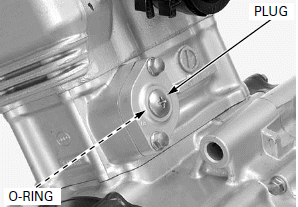
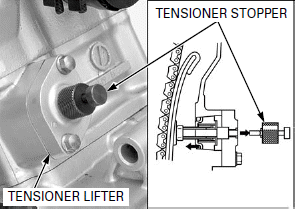
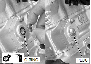
Remove the cam chain tensioner lifter plug and O-ring.
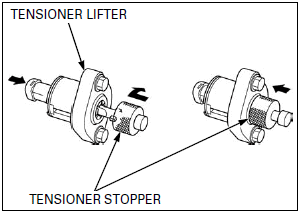
Turn the cam chain tensioner lifter shaft fully in (clockwise) and secure it using a tensioner stopper to prevent damaging the cam chain.
TOOL: Tensioner stopper 070MG-0010100
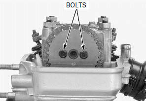
Be careful not to let the cam sprocket bolts fall into the crankcase.
Remove the cam sprocket bolts.
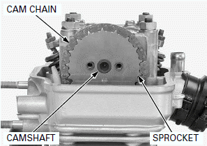
Be careful not to let the cam sprocket fall into the crankcase.
Remove the cam sprocket to the camshaft.
Attach a piece of wire to the cam chain to prevent it from falling into the crankcase.
Remove the sprocket from the cam chain.
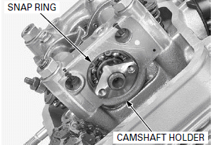
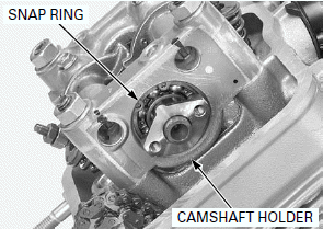
Remove the snap ring from the camshaft holder.
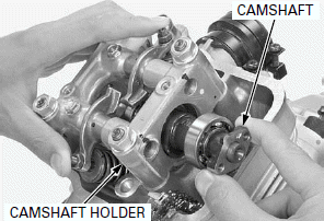
Remove the camshaft from the camshaft holder while holding the rocker arms to make a good access for camshaft removal.
INSPECTION
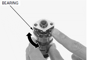
CAMSHAFT BEARING
Turn the outer race of each bearing with your finger.
The bearings should turn smoothly and quietly.
Also check that the bearing inner race fits tightly on the camshaft.
Replace the camshaft assembly if the bearings do not turn smoothly, quietly or if they fit loosely on the camshaft.
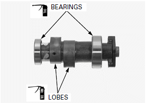
CAM LOBE
Check the cam lobe surfaces for scoring or evidence of insufficient lubricant.
Measure the height of each cam lobe.
SERVICE LIMITS:
IN: 29.05 mm (1.144 in)
EX: 28.85 mm (1.136 in)
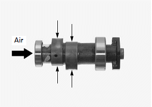
Clean the oil passage of the camshaft using a compressed air.
INSTALLATION
Apply engine oil to the camshaft bearings rotating area.
Apply molybdenum oil solution to the cam lobes.
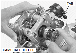
Make sure the tab of the camshaft facing upward.
Install the camshaft into the camshaft holder while holding the rocker arms to make a good access for camshaft installation.
Make sure the snap ring is firmly seated in the groove.
Install the snap ring into the groove of the camshaft holder.
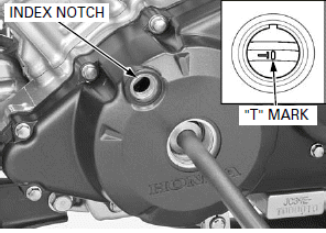
Be careful not to jam the cam chain and timing sprocket on the crankshaft when rotating the crankshaft.
Rotate the crankshaft counterclockwise, and align the "T" mark on the flywheel with the index notch on the left crankcase cover.
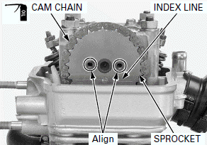
Apply engine oil to the cam chain entire surface.
Install the cam chain over the cam sprocket so that the index line of the cam sprocket is flush with the cylinder head upper surface as shown.
Align the bolt holes in the cam sprocket and camshaft.
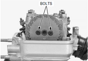
Be careful not to let the cam sprocket bolts fall into the crankcase.
Install and tighten the cam sprocket mounting bolts to the specified torque by holding the crankshaft.
TORQUE: 9.0 N-m (0.9 kgf-m, 6.6 lbf-ft)
Remove the tensioner stopper from the cam chain tensioner lifter.
Apply engine oil to a new O-ring and install it to the cam chain tensioner lifter.
Install and tighten the cam chain tensioner lifter plug to the specified torque.
TORQUE: 4.0 N-m (0.4 kgf-m, 3.0 lbf-ft)
Install the cylinder head cover.
CAMSHAFT HOLDER
REMOVAL
Remove the cylinder head cover.
Remove the cam sprocket.
Loosen the cylinder head bolts alternately in several steps.
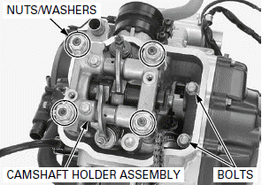
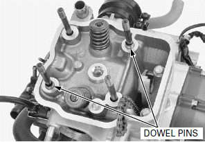
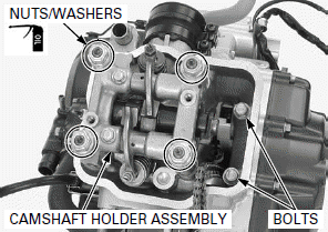
Be careful not to let the camshaft holder mounting nuts and washers fall into the crankcase.
Loosen the camshaft holder mounting nuts in a crisscross pattern in several steps, and remove the washers and camshaft holder assembly.
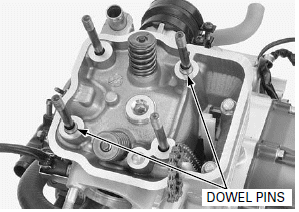
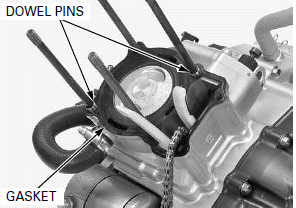
Remove the dowel pins from the cylinder head.
DISASSEMBLY
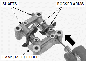
Remove the camshaft.
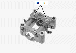
Remove the rocker arm shaft stopper bolts.
Push the rocker arm shafts from the right side as shown.
Remove the rocker arm shafts and rocker arms from the camshaft holder.
INSPECTION
ROCKER ARM/ROCKER ARM SHAFT
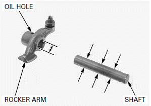
Check the sliding surface of each rocker arm and rocker arm shaft for wear or damage.
Check the oil hole for clog of each rocker arm.
Measure the rocker arm I.D.
SERVICE LIMIT: 10.10 mm (0.398 in)
Measure the rocker arm shaft O.D. at three points.
SERVICE LIMIT: 9.75 mm (0.384 in)
Calculate the rocker arm-to-shaft clearance.
SERVICE LIMIT: 0.10 mm (0.004 in)
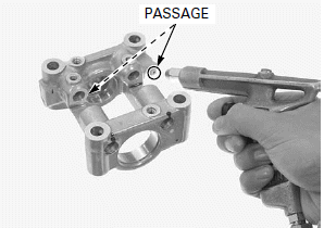
Clean the oil passages of the camshaft holder using a compressed air.
Check the oil passage for clogs.
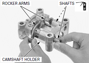
ASSEMBLY
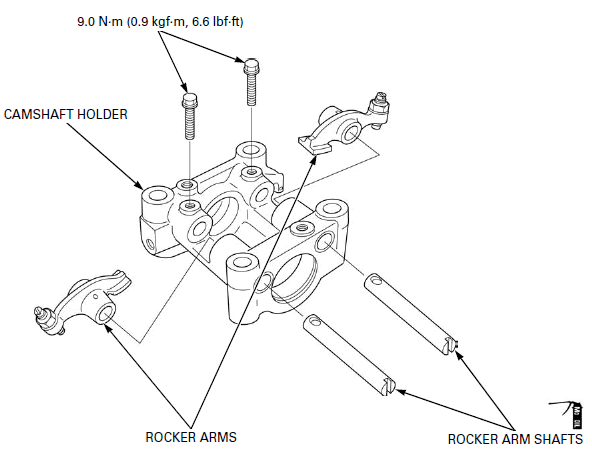
Apply molybdenum oil solution to each rocker arm shaft outer surface.
Set the rocker arm into the camshaft holder with the camshaft contact area facing the cylinder head as shown, then install the rocker arm shaft with the threads facing the bolt hole into the camshaft holder through the rocker arm.
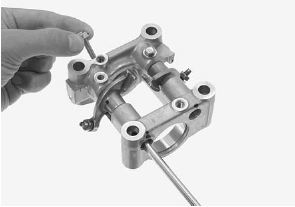
Align the bolt holes in the camshaft holder and rocker arm shaft using a flat blade screwdriver.
Install and tighten the rocker arm shaft stopper bolts to the specified torque.
TORQUE: 9.0 N-m (0.9 kgf-m, 6.6 lbf-ft)
Install the camshaft.
INSTALLATION
Install the dowel pins to the cylinder head.
Install the camshaft holder onto the cylinder head.
Apply engine oil to the camshaft holder mounting nut threads and seating surface.
Be careful not to let the washers and camshaft holder mounting nuts fall into the crankcase.
Install the washers and camshaft holder mounting nuts and tighten the nuts to the specified torque in a crisscross pattern in several steps.
TORQUE: 29 N-m (3.0 kgf-m, 21 lbf-ft)
Tighten the cylinder head bolts alternately in several steps.
Install the following:
- Cam sprocket
- Cylinder head cover
CYLINDER HEAD

If the O2 sensor cap is disconnected, replace the O2 sensor cord with a new one.
REMOVAL
Remove the following:
- Engine
- Camshaft holder
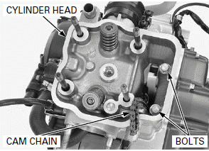
Be careful not to let the cylinder head bolts fall into the crankcase.
Remove the cylinder head bolts and cylinder head.
NOTE:
- Attach a piece of wire to the cam chain to prevent it from falling into the crankcase.
- Do not strike the cylinder too hard and do not damage the mating surface with a screwdriver.
Remove the dowel pins and gasket.
DISASSEMBLY
Remove the following:
- Spark plug
- O2 sensor
If the O2 sensor cap is disconnected, replace the O2 sensor cord with a new one.
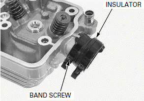
Loosen the insulator band screw and remove the throttle body insulator.
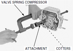
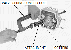
To prevent loss of tension, do not compress the valve springs more than necessary to remove the cotters.
Remove the valve spring cotters using the special tools.
TOOLS:
Valve spring compressor 07757-0010000
Valve spring compressor attachment 07959-KM30101
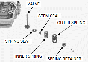
Mark all parts during disassembly so they can be installed in their original locations.
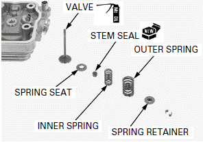
Remove the following:
- Spring retainer
- Inner and outer valve springs
- Valve
- Stem seal
- Spring seat
INSPECTION
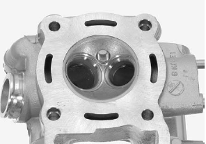
CYLINDER HEAD
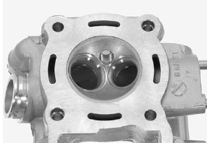
Use care not to scratch the combustion chamber or head gasket surface.
Remove the carbon deposits from the combustion chamber or exhaust port.
Check the spark plug hole and valve area for cracks.
Replace the cylinder head if necessary.
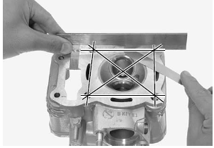
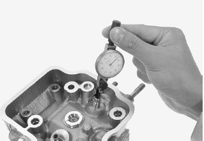
Be careful not to damage the gasket surface.
Check the cylinder head for warpage with a straight edge and feeler gauge.
SERVICE LIMIT: 0.05 mm (0.002 in)
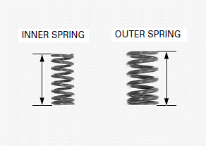
VALVE SPRING
Check the valve springs for fatigue or damage.
Measure the free length of the inner and outer valve springs.
SERVICE LIMITS:
INNER: 31.0 mm (1.22 in)
OUTER: 34.0 mm (1.34 in)
Replace the springs if they are shorter than the service limits.
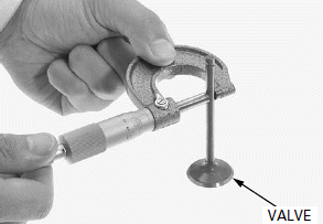
VALVE
Check that the valve moves smoothly in the guide.
Inspect each valve for bending, burning, scratches or abnormal stem wear.
Measure and record each valve stem O.D.
SERVICE LIMITS:
IN: 4.863 mm (0.1915 in)
EX: 4.853 mm (0.1911 in)
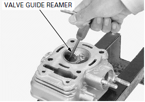
VALVE GUIDE
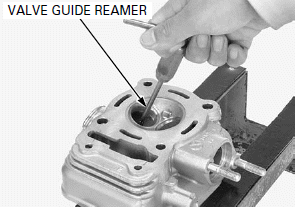
Ream the valve guide to remove any carbon build-p before measuring the guide I.D.
NOTE:
- Use cutting oil on the reamer during this operation.
- Take care not to tilt or lean the reamer in the guide while reaming. Otherwise, the valves may be installed slanted, causing oil leakage from the stem seal and improper valve seat contact. This may prevent valve seat refacing.
- Insert the reamer from the combustion chamber side of the head and always rotate the reamer clockwise.
TOOL: Valve guide reamer, 5.0 mm 07984-MA60001
Measure each valve guide I.D. and record it.
SERVICE LIMIT: IN/EX: 5.04 mm (0.198 in)
Subtract each valve stem O.D. from the corresponding guide I.D. to obtain the stem-to-guide clearance.
SERVICE LIMITS:
IN: 0.065 mm (0.0026 in)
EX: 0.075 mm (0.0030 in)
If the stem-to-guide clearance exceeds the service limit, determine if a new guide with standard dimensions would bring the clearance within tolerance.
If so, replace any guides as necessary and ream to fit.
If the stem-to-guide clearance exceeds the service limit with a new guide, also replace the valve.
Inspect and reface the valve seats whenever the valve guides are replaced.
VALVE GUIDE REPLACEMENT
NOTE:
Refinish the valve seats whenever the valve guides are replaced to prevent uneven seating.
Chill new valve guides in a freezer section of refrigerator for about an hour.
Do not use a torch to heat the cylinder head; it may cause warping.
Heat the cylinder head to 130 - 140ºC (266 - 284ºF) with a hot plate or oven. Do not heat the cylinder head beyond 150ºC (302ºF). Use temperature indicator sticks, available from welding supply stores, to be sure the cylinder head is heated to the proper temperature.
To avoid burns, wear insulated gloves when handling the heated cylinder head.
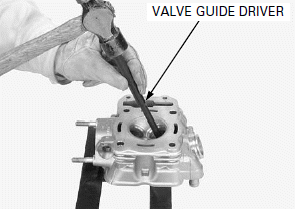
Support the cylinder head and drive out the valve guides from the combustion chamber side of the cylinder head.
TOOL: Valve guide driver, 5.0 mm 07942-8920000
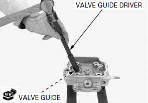
While the cylinder head is still heated, take off a new valve guides from the freezer.
Drive the guides in the cylinder head from the camshaft side.
TOOL: Valve guide driver 07743-0020000
After installing the valve guides, measure the valve guide height from the cylinder head.
SPECIFIED HEIGHT:
IN: 11.5 - 11.7 mm (0.45 - 0.46 in)
EX: 12.3 - 12.5 mm (0.48 - 0.49 in)
Let the cylinder head cool to room temperature.
Ream a new valve guides.
TOOL: Valve guide reamer, 5.0 mm 07984-MA60001
NOTE:
- Use cutting oil on the reamer during this operation.
- Take care not to tilt or lean the reamer in the guide while reaming. Otherwise, the valves may be installed slanted, causing oil leakage from the stem seal and improper valve seat contact. This may prevent valve seat refacing.
- Insert the reamer from the combustion chamber side of the head and always rotate the reamer clockwise.
Clean the cylinder head thoroughly to remove any metal particles after reaming and reface the valve seat.
VALVE SEAT INSPECTION
Clean the intake and exhaust valves thoroughly to remove carbon deposits.
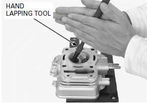
Apply thin coat of Prussian Blue to each valve face.
Tap the valve against the valve seat several times using a hand lapping tool without rotating valve to make a clear pattern.
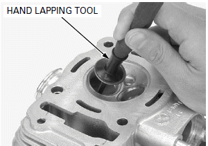
Remove the valve and inspect the valve seat face.
NOTE:
The valve cannot be ground. If the valve face is burned or badly worn or if it contacts the seat unevenly, replace the valve.
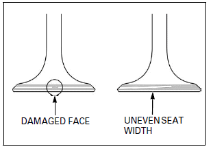
Inspect the valve seat face for:
- Damaged face:
- Replace the valve and reface the valve seat.
- Uneven seat width:
- Replace the valve and reface the valve seat.
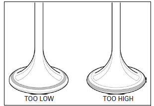
- Contact area (too high or too low area):
- Reface the valve seat.
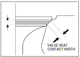
Inspect the width of the valve seat.
The valve seat contact should be within the specified width and even all around the circumference.
STANDARD: 0.90 - 1.10 mm (0.035 - 0.043 in)
SERVICE LIMIT: 1.50 mm (0.059 in)
If the valve seat width is not within specification, reface the valve seat.
VALVE SEAT REFACING
NOTE:
- Follow the refacing manufacturer's operating instructions.
- Reface the valve seat whenever the valve guide has been replaced.
- Be careful not to grind the seat more than necessary.
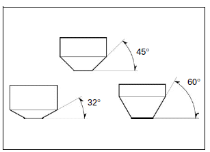
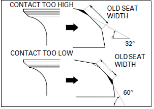
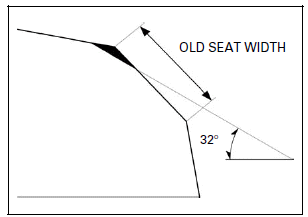
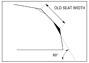
If the contact area is too high on the valve, the seat must be lowered using a 32º flat cutter.
If the contact area is too low on the valve, the seat must be raised using a 60º inner cutter.
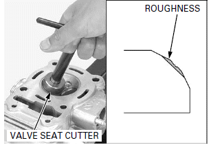
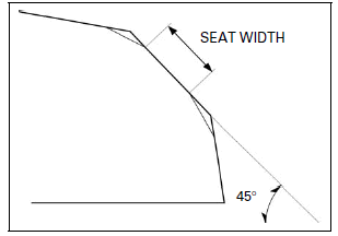
Reface the valve seat with a 45º cutter when a valve guide is replaced.
Use a 45º cutter, remove any roughness or irregularities from the seat.
TOOLS:
Seat cutter, 24 mm (45º EX) 07780-0010600
Seat cutter, 29 mm (45º IN) 07780-0010300
Cutter holder, 5.0 mm 07781-0010400
Using 32º cutter, remove the top 1/4 of the existing valve seat material.
TOOLS:
Flat cutter, 27 mm (32º EX) 07780-0013300
Flat cutter, 30 mm (32º IN) 07780-0012200
Cutter holder, 5.0 mm 07781-0010400
Using 60º cutter, remove the bottom 1/4 of the old seat.
Remove the cutter and inspect the area you have just removed.
TOOLS:
Interior cutter, 26 mm (60º EX) 07780-0014500
Interior cutter, 30 mm (60º IN) 07780-0014000
Cutter holder, 5.0 mm 07781-0010400
Using a 45º cutter, cut the seat to proper width.
Make sure that all pitting and irregularities are removed.
Refinish if necessary.
STANDARD SEAT WIDTH: 0.90 - 1.10 mm (0.035 - 0.043 in)
After cutting the seat, apply lapping compound to the valve face and lap the valve using light pressure.
NOTE:
- Excessive lapping pressure may deform or damage the seat.
- Change the angle of lapping tool frequently to prevent uneven seat wear.
- Lapping compound can cause damage if it enters between the valve stem and guide.
After lapping, wash any residual compound off the cylinder head and valve.
Recheck the seat contact after lapping.
ASSEMBLY
Clean the cylinder head assembly with solvent and blow through all oil passages with compressed air.
Install the spring seats and new valve stem seals.
Lubricate each valve stem and stem end with molybdenum oil solution.
To avoid damage to the seal, turn the valve slowly when inserting.
Insert the intake and exhaust valves into the valve guides.
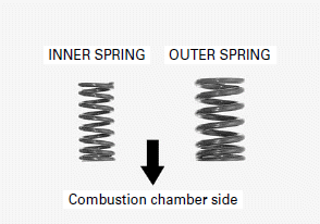
Install the inner and outer valve springs with the tightly wound coils should face toward the combustion chamber.
Grease the cotters to ease installation.
To prevent loss of tension, do not compress the valve spring more than necessary.
Install the spring retainer.
Compress the valve spring using the special tools and install the valve cotters.
TOOLS:
Valve spring compressor 07757-0010000
Valve spring compressor attachment 07959-KM30101
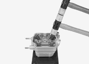
Support the cylinder head above the work bench surface to prevent valve damage.
Tap the valve stems gently with two plastic hammer to firmly seat the cotters.
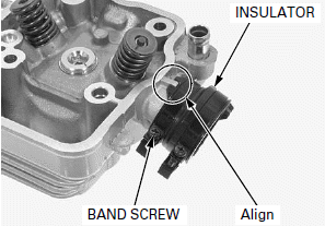
Install the throttle body insulator by aligning the groove of the throttle body insulator with the tab of the cylinder head.
Tighten the insulator band screw.
Install the following:
- Spark plug
- O2 sensor
INSTALLATION
Do not allow dust and dirt to enter the crankcase.
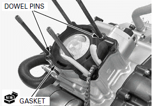
Clean any gasket material from the cylinder mating surfaces.
Install the dowel pins and new gasket.
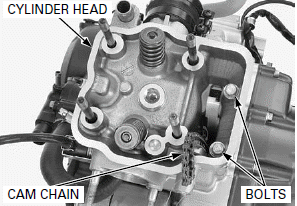
Route the cam chain through the cylinder head and install the cylinder head onto the cylinder.
Be careful not to let the cylinder head bolts fall into the crankcase.
Loosely install the cylinder head bolts.
Install the following:
- Camshaft holder
- Engine
See also:
 Honda CBR125RW - Service manual > Engine Removal/Installation
COMPONENT LOCATION
Honda CBR125RW - Service manual > Cylinder/Piston
COMPONENT LOCATION SERVICE INFORMATION
 BMW G310GS
 Honda CBR125RW
 Husqvarna 401 Vitpilen
 KTM 890 Duke R
 Mash Dirt Track 650
 Peugeot Kisbee
 Yamaha Tracer MT-09
 Honda CBR125RW
 Peugeot Kisbee
 Yamaha Tracer MT-09