 Honda CBR125RW - Service manual > Cylinder/Piston
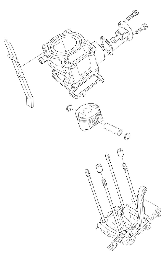
COMPONENT LOCATION
SERVICE INFORMATION
GENERAL
- This section covers maintenance of the cylinder and piston. To service these parts, the engine must be removed from the frame.
- Take care not to damage the cylinder wall and piston.
- Be careful not to damage the mating surfaces when removing the cylinder. Do not strike the cylinder too hard during removal.
- Camshaft and rocker arm lubricating oil is fed through an oil passage in the cylinder. Clean the oil passage before installing cylinder.
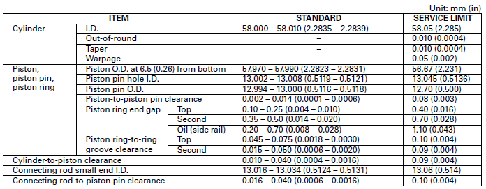
SPECIFICATIONS
TORQUE VALUE
Cylinder stud bolt -
TROUBLESHOOTING
Compression too low, hard starting or poor performance at low speed
- Leaking or damaged cylinder head gasket
- Worn, stuck or broken piston rings
- Worn or damaged cylinder and piston
- Loose spark plug
Compression too high, overheating or knocking
- Excessive carbon built-up on piston or combustion chamber
Excessive smoke
- Faulty cylinder, piston and piston rings
- Improper installation of piston rings
- Scored or scratched piston or cylinder wall
Abnormal noise (piston)
- Worn piston pin or piston pin hole
- Faulty cylinder, piston or piston ring
- Worn connecting rod small end
CYLINDER/PISTON
CYLINDER REMOVAL
Remove the cylinder head.
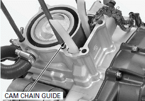
Remove the cam chain guide.
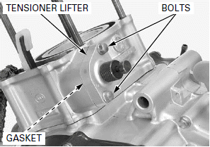
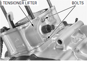
Remove the cam chain tensioner lifter mounting bolts.
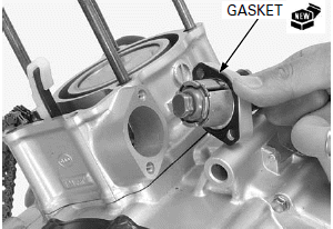
Remove the cam chain tensioner lifter and gasket.
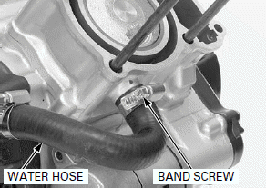
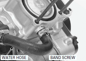
Loosen the water hose band screw and disconnect the water hose.
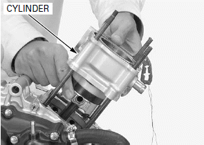
Lift the cylinder and remove it, being careful not to damage the piston with the stud bolts.
NOTE:
- Attach a piece of wire to the cam chain to prevent it from falling into the crankcase.
- Do not strike the cylinder too hard and do not damage the mating surface with a screwdriver.
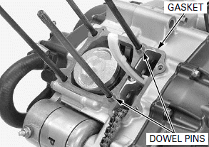
Remove the dowel pins and gasket.
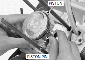
PISTON REMOVAL
Place a clean shop towel over the crankcase to prevent the piston pin clips from falling into the crankcase.
Remove the piston pin clips with pliers.
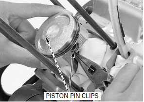
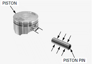
Push the piston pin out of the piston and connecting rod, and remove the piston.
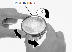
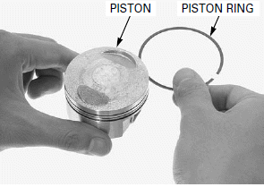
Spread each piston ring and remove it by lifting up a point opposite the gap.
NOTE:
- Do not damage the piston ring by spreading the ends too far.
- Be careful not to damage the piston when the piston ring removal.
Never use a wire brush; it will scratch the grooves.
Clean carbon deposits from the piston ring grooves with a used piston ring that will be discarded.
INSPECTION
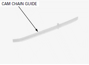
CAM CHAIN GUIDE
Check the cam chain guide for excessive wear or damage, replace if necessary.
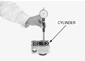
CYLINDER
Check the cylinder wall for scratches and wear.
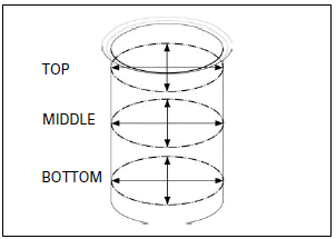
Measure the cylinder I.D. at three levels on the X and Y axes. Take the maximum reading to determine the cylinder wear.
SERVICE LIMIT: 58.05 mm (2.285 in)
Calculate the cylinder-to-piston clearance.
Calculate the cylinder taper and out-of-round at three levels on the X and Y axis. Take the maximum reading to determine the taper and out-of-round.
SERVICE LIMITS:
Taper: 0.010 mm(0.0004 in)
Out-of-round: 0.010 mm (0.0004 in)
The cylinder must be rebored and an oversize piston fitted if the service limits are exceeded.
These parts numbers may be change without written permission.
The following oversize pistons are available:
0.25 mm (0.010 in): 13012-KGH-305
0.50 mm (0.020 in): 13013-KGH-305
0.75 mm (0.030 in): 13014-KGH-305
1.00 mm (0.040 in): 13015-KGH-305
The cylinder-to-piston clearance for the oversize piston must be: 0.010 - 0.040 mm (0.0004 - 0.0016 in).
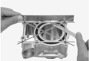
Check the top of the cylinder for warpage with a straight edge and feeler gauge across the stud and bolt holes.
SERVICE LIMIT: 0.05 mm (0.002 in)
PISTON/PISTON RING
Check the piston for cracks or other damage.
Check the ring grooves for excessive wear and carbon build-up.
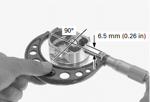
Measure each piston O.D. at a point 6.5 mm (0.26 in) from the bottom and 90º to the piston pin hole.
SERVICE LIMIT: 56.67 mm (2.231 in)
Calculate the cylinder-to-piston clearance. Take the maximum reading to determine the clearance (Cylinder I.D.).
SERVICE LIMIT: 0.09 mm (0.004 in)
Measure piston pin hole I.D.
SERVICE LIMIT: 13.045 mm (0.5136 in)
Measure the piston pin O.D. at three points.
SERVICE LIMIT: 12.70 mm (0.500 in)
Calculate the piston-to-piston pin clearance.
SERVICE LIMIT: 0.08 mm (0.003 in)
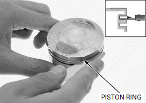
Always replace the piston rings as a set.
Inspect the piston rings for smooth movement by rotating them. The rings should be able to move in their grooves without catching.
Push in the ring until the outer surface of the piston ring is nearly flush with the piston and measure the ring-to-ring groove clearance using a feeler gauge.
SERVICE LIMITS:
Top: 0.10 mm (0.004 in)
Second: 0.09 mm (0.004 in)
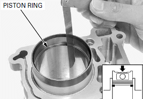
Insert the piston ring into the bottom of the cylinder squarely using the piston crown.
Measure the piston ring end gap.
SERVICE LIMITS:
Top: 0.40 mm (0.016 in)
Second: 0.70 mm (0.028 in)
Oil: 1.10 mm (0.043 in)
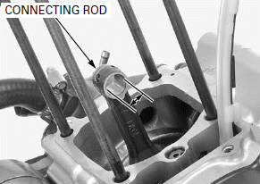
CONNECTING ROD
Measure the connecting rod small end I.D.
SERVICE LIMIT: 13.06 mm (0.514 in)
Calculate the connecting rod-to-piston pin clearance.
SERVICE LIMIT: 0.10 mm (0.004 in)
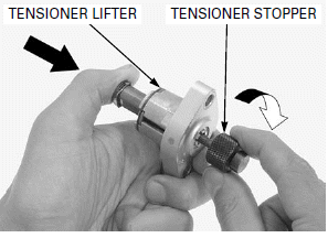
CAM CHAIN TENSIONER LIDFTER
Check the lifter operation:
- The cam chain tensioner lifter shaft should not go into the cam chain tensioner lifter body when it is pushed.
- When it is turned clockwise with a tensioner stopper, the cam chain tensioner lifter shaft should be pulled into the cam chain tensioner lifter body. The cam chain tensioner lifter shaft should spring out of the cam chain tensioner lifter body as soon as the tensioner stopper is released.
TOOL: Tensioner stopper 070MG-0010100
STUD BOLT REPLACEMENT
Thread two nuts onto the stud and tighten them together, and use a wrench on them to turn the stud bolt out.
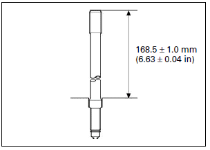
Install new stud bolts into the crankcase as shown.
After installing the stud bolts, check that the length from the bolt head to the crankcase surface is within specification.
PISTON INSTALLATION
Apply engine oil to the piston ring entire surface.
Be careful not to damage the piston and rings.
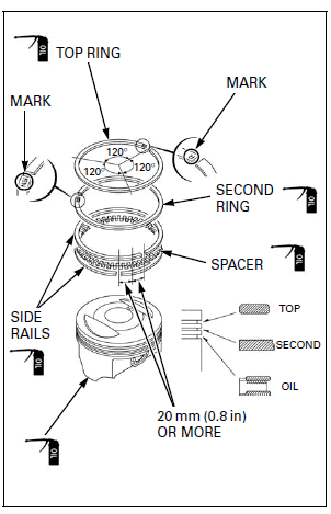
NOTE:
- Do not confuse the top and second rings.
- To install the oil ring, install the spacer first, then install the side rails.
Stagger the piston ring end gaps 120º apart from each other.
Stagger the side rail end gaps as shown.
Apply engine oil to the piston outer surface.
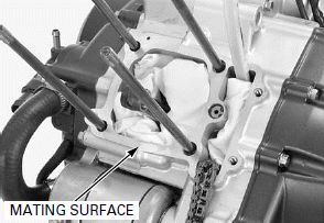
When cleaning the cylinder mating surface, place a shop towel over the cylinder opening to prevent dust or dirt enter the crankcase.
Clean any gasket material from the cylinder mating surface of the crankcase.
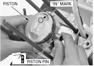
Apply molybdenum oil solution to the piston pin outer surfaces.
Install the piston with its "IN" mark facing intake side.
Install the piston pin.
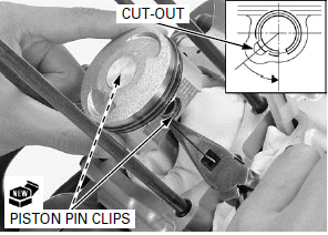
Install new piston pin clips into the grooves of the piston pin hole.
NOTE:
- Always use new piston pin clips. Reinstalling used piston pin clips may lead to serious engine damage.
- Set the piston pin clip in the groove properly.
- Do not align the clip's end gap with the piston cut-out.
CYLINDER INSTALLATION
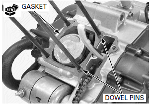
Install the dowel pins and a new gasket.
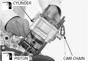
Apply engine oil to the cylinder inner surface and piston outer surface.
Be careful not to damage the piston rings and cylinder wall.
Route the cam chain through the cylinder and install the cylinder over the piston while compressing the piston rings with your fingers.
Connect the water hose and tighten the water hose band screw.
Install a new gasket on the cam chain tensioner lifter and install them to the cylinder.
Install and tighten the cam chain tensioner mounting bolts.
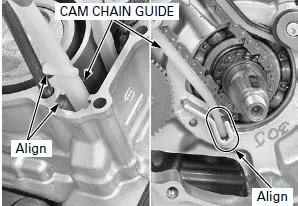
Install the cam chain guide, aligning its tabs with the cylinder grooves and its end with the left crankcase groove.
Install the cylinder head.
See also:
 Honda CBR125RW - Service manual > Cylinder Head/Valves
COMPONENT LOCATION SERVICE INFORMATION
Honda CBR125RW - Service manual > Clutch/Gearshift Linkage
COMPONENT LOCATION SERVICE INFORMATION
 BMW G310GS
 Honda CBR125RW
 Husqvarna 401 Vitpilen
 KTM 890 Duke R
 Mash Dirt Track 650
 Peugeot Kisbee
 Yamaha Tracer MT-09
 Honda CBR125RW
 Peugeot Kisbee
 Yamaha Tracer MT-09