 Honda CBR125RW - Service manual > Engine Removal/Installation
COMPONENT LOCATION
SERVICE INFORMATION
GENERAL
- A hoist or equivalent is required to support the motorcycle when removing and installing the engine.
- When removing/installing the engine, tape the frame around the engine beforehand for frame protection.
- The following components can be serviced with the engine installed in
the frame.
- Oil pump
- Camshaft
- Clutch
- Gearshift linkage
- Stator/CKP sensor
- Flywheel
- Starter motor
- The following components require engine removal for service.
- Cylinder head/valves
- Cylinder/piston
- Crankshaft/balancer
- Transmission
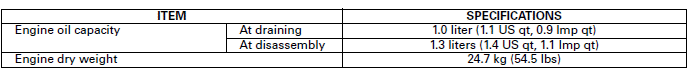
SPECIFICATIONS
TORQUE VALUES
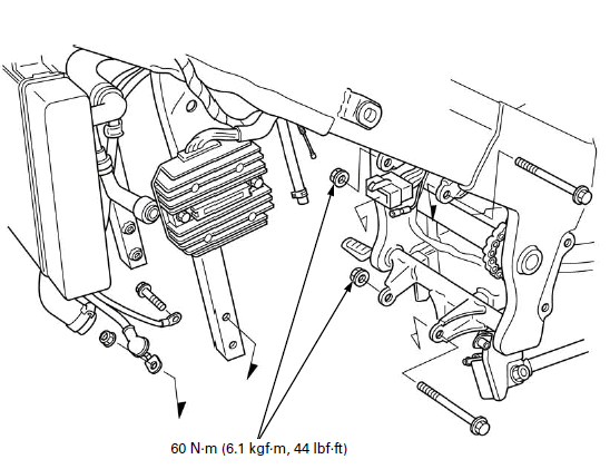
Engine hanger nut
(upper) 60 N-m (6.1 kgf-m, 44 lbf-ft)
(lower) 60 N-m (6.1 kgf-m, 44 lbf-ft)
(front) 60 N-m (6.1 kgf-m, 44 lbf-ft)
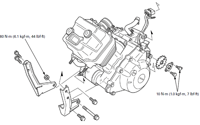
Drive sprocket fixing plate bolt 10 N-m (1.0 kgf-m, 7 lbf-ft)
Water hose band screw -
ENGINE REMOVAL
Drain the engine oil.
Drain the coolant.
Remove the following:
- Middle cowl
- Gearshift arm and left step holder
- Throttle body
- Exhaust pipe/muffler
- Drive sprocket cover
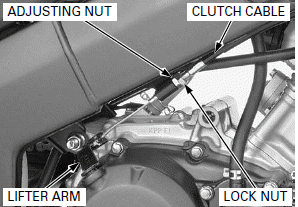
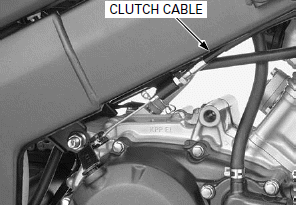
Loosen the lock nut and adjusting nut, then disconnect the clutch cable from the clutch lifter arm.
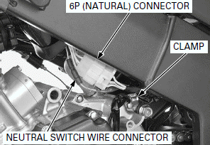
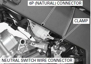
Disconnect the alternator/CKP sensor 6P (Natural) connector and neutral switch wire connector.
Release the alternator/CKP sensor and neutral switch wires from the clamp.
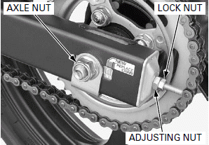
Loosen the axle nut, lock nuts and adjusting nuts.
Push the rear wheel forward and make a drive chain slack fully.
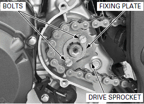
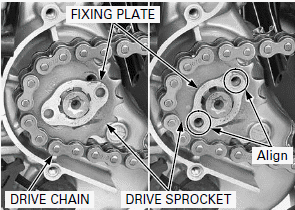
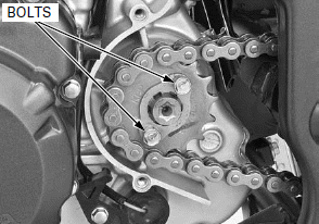
Remove the bolts, fixing plate and drive sprocket.
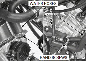
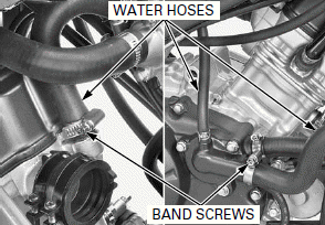
Loosen the water hose band screws and disconnect the water hoses.
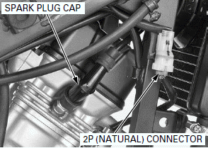
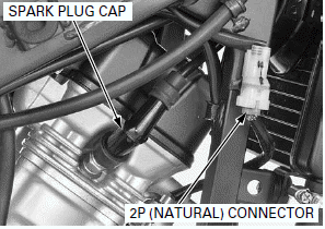
Do not disconnect the O2 sensor cap from the O2 sensor.
Disconnect the O2 sensor 2P (Natural) connector and spark plug cap.

If the O2 sensor cap is disconnected, replace the O2 sensor cord with a new one.
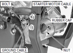
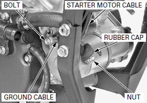
Release the rubber cap.
Remove the starter motor terminal nut and starter motor cable.
Remove the starter motor mounting bolt and ground cable.
The jack height must be continually adjusted to relieve stress for ease of bolt removal.
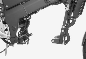
Support the engine using a jack or other adjustable support to ease of engine hanger bolts removal.
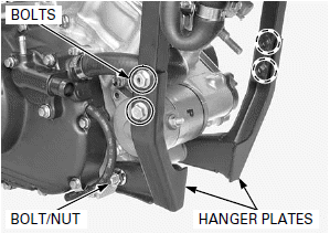
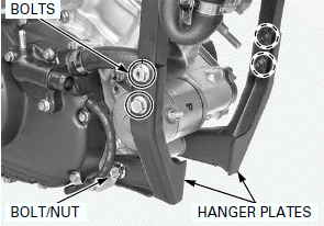
Remove the following:
- Front engine hanger bolt and nut
- Front engine hanger plate bolts
- Front engine hanger plates
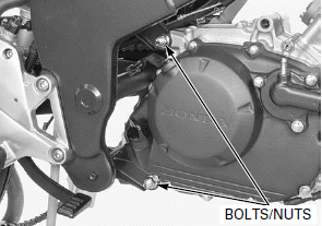
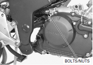
Remove the upper and lower engine hanger bolts and nuts.
During engine removal, hold the engine securely and be careful not to damage the frame and engine.
Remove the engine from the frame.
ENGINE INSTALLATION
NOTE:
- Note the direction of the engine hanger bolts.
- Place the jack or other adjustable support under the engine.
- The jack height must be continually adjusted to relieve stress for ease bolt installation.
- Carefully align the mounting points with the jack to prevent damage to engine, frame, water hose, wires and cables.
- All the engine mounting bolts and nuts loosely install, then tighten the bolts and nuts to the specified torque.
- Route the water hose, wires and cables properly.
During engine installation, hold the engine securely and be careful not to damage the frame and engine.
Place the engine in the frame, then loosely install all the bolts, nuts and front engine hanger plates.
Tighten the upper and lower engine hanger nuts to the specified torque.
TORQUE:
Upper engine hanger nut: 60 N-m (6.1 kgf-m, 44 lbf-ft)
Lower engine hanger nut: 60 N-m (6.1 kgf-m, 44 lbf-ft)
Tighten the front engine hanger plates bolts securely.
Tighten the front engine hanger nuts to the specified torque.
TORQUE: 60 N-m (6.1 kgf-m, 44 lbf-ft)
Install the ground cable and starter motor mounting bolt.
Tighten the mounting bolt securely.
Install the starter motor cable and starter motor terminal nut.
Tighten the terminal nut securely and reposition the rubber cap properly on the starter motor terminal.
Connect the spark plug cap and O2 sensor 2P (Natural) connector.
If the O2 sensor cap is disconnected, replace the O2 sensor cord with a new one.
Connect the water hoses and tighten the water hose band screws.
Install the drive chain over the drive sprocket.
Install the drive sprocket to the countershaft.
Install the fixing plate.
Rotate the fixing plate and align the hole in the plate with the bolt hole in the drive sprocket.
Install and tighten the drive sprocket fixing plate bolts to the specified torque.
TORQUE: 10 N-m (1.0 kgf-m, 7 lbf-ft)
Connect the alternator/CKP sensor 6P (Natural) connector and neutral switch wire connector.
Route the wires properly.
Install the alternator/CKP sensor and neutral switch wires from the clamp.
Connect the clutch cable.
Install the following:
- Drive sprocket cover
- Exhaust pipe/muffler
- Throttle body
- Gearshift arm and left step holder
- Middle cowl
Inspect the following:
- Drive chain slack
- Throttle grip freeplay
- Clutch lever freeplay
Fill the engine with the recommended engine oil.
Fill the recommended coolant mixture to the filler neck and bleed the air.
See also:
 Honda CBR125RW - Service manual > Cooling System
SYSTEM FLOW PATTERN RESERVE TANK SIPHON HOSE THERMOSTAT WATER HOSES RADIATOR WATER PUMP
Honda CBR125RW - Service manual > Cylinder Head/Valves
COMPONENT LOCATION SERVICE INFORMATION
 BMW G310GS
 Honda CBR125RW
 Husqvarna 401 Vitpilen
 KTM 890 Duke R
 Mash Dirt Track 650
 Peugeot Kisbee
 Yamaha Tracer MT-09
 Honda CBR125RW
 Peugeot Kisbee
 Yamaha Tracer MT-09